Imported Mesh
In this example we will import a mesh from a CAD file and use FEniCS to model its displacement. This file was created in Autodesk Inventor and exported as an .igs file, which can be downloaded here. To convert it to a a Gmsh .msh file, run this line in the command line:
gmsh -3 -clmax 1 -o mesh.msh mesh_1.igs
The -3 flag creates a 3D mesh and the -clmax 1 flag sets the max size of an element to 1 to help with the smoothing of the holes in the model. We then use another command to convert the .msh file to a .xml file for Dolfin:
dolfin-convert mesh.msh mesh.xml
We can now import the mesh into a FEniCS script and write it out to a .pvd file with no marked regions to preview the mesh geometry:
from dolfin import *

mesh = Mesh('mesh.xml')

folder_name = './mesh1_results'

regions = MeshFunction('size_t', mesh, mesh.topology().dim()-1)
regions.set_all(0)

regionfile = File('%s/regions.pvd' % folder_name)
regionfile << regions
We get this when we open the .pvd file in ParaView.
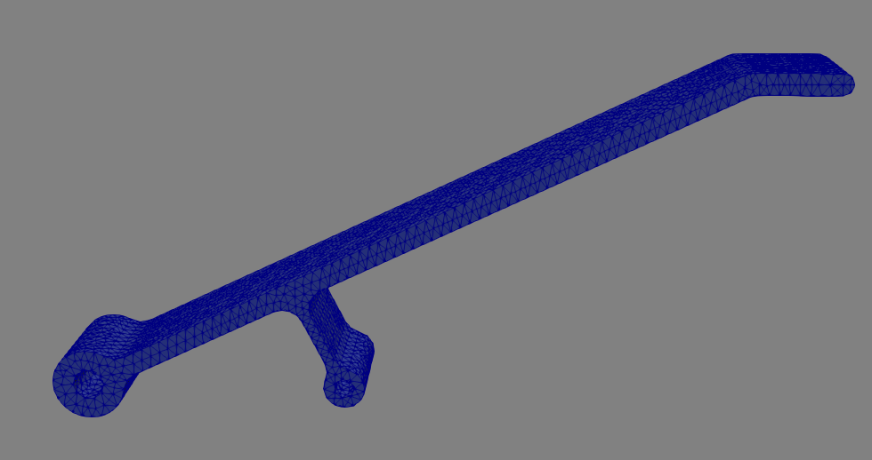
This piece is a small aluminum component designed to hold a load of up to \(20\text{N}\) on the top platform while deflecting less than \(1\text{mm}\). Let’s use FEniCS to see if it meets the specifications.
First, let’s define the fixed regions and loaded regions in the mesh:
from dolfin import *
import numpy as np
import region_selector_3d as rs

mesh = Mesh('mesh.xml')
folder_name = './mesh1_results'

fixedPin1 = rs.GetCylindricalRegion(Point(0.0,0.0,5.0), Point(0.0,0.0,-5.0), 1.6)
fixedPin2 = rs.GetCylindricalRegion(Point(25.0,0.0,5.0), Point(25.0,0.0,-5.0), 1.1)
loadFace = rs.GetPlanarBoundary.from_coord('y', 31.0)

regions = MeshFunction('size_t', mesh, mesh.topology().dim()-1)
regions.set_all(0)
fixedPin1.mark(regions, 1)
fixedPin2.mark(regions, 1)
loadFace.mark(regions, 2)

regionfile = File('%s/regions.pvd' % folder_name)
regionfile << regions

ds = Measure('ds', domain = mesh, subdomain_data = regions)
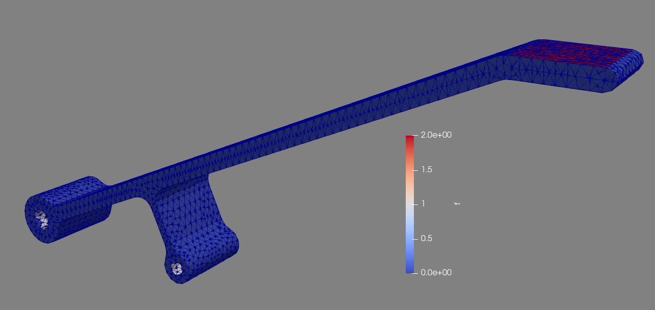
We can now view the marked faces in ParaView:
We now define the load and material properties and set up the simulation as in the previous examples. Note that in this case we cannot use the area() method of the planar boundary class because it was not defined using a set of four corners that perfectly fit the mesh, so the returned area of the region won’t match the actual selected area. Instead, we use the assemble() function which returns the integral of what’s passed to it. In this case, the area is \(\int_\Omega 1*ds\) where \(\Omega\) is the load region. The area of the load region can be found with ``assemble(Constant(1.0)*ds(2))`.
E = 69800.0
nu = 0.33
mu = E / (2.0 * (1.0 + nu))
lmbda = E * nu / ((1.0 + nu) * (1.0 - 2.0*nu))

appliedLoad = Constant((0.0,-20.0,0.0)) # [N]
loadArea = assemble(Constant(1.0) * ds(2))
scaledLoad = appliedLoad / loadArea

def eps(u):
return sym(grad(u))

def sigma(u):
return lmbda*tr(eps(u)) * Identity(mesh.topology().dim()) + 2.0*mu*eps(u)

V = VectorFunctionSpace(mesh, "Lagrange", 2)
du = TrialFunction(V)
u = Function(V, name = "Displacement")
v = TestFunction(V)

a = inner(sigma(du), eps(v))*dx
L = dot(scaledLoad, v) * ds(2)
We define two separate boundary conditions, one for each pin. For simplicity’s sake we treat the surfaces which contact the pins as fixed rather than pinned, which in this example is a good enough approximation:
bc1 = DirichletBC(V, Constant((0.0,0.0,0.0)), fixedPin1)
bc2 = DirichletBC(V, Constant((0.0,0.0,0.0)), fixedPin2)

solve(a == L, u, [bc1, bc2])

u.rename("Displacement", "Displacement")
xdmf_file = XDMFFile('%s/results.xdmf' % folder_name)
xdmf_file.write(u,1.0)
When we run the simulation we find that the maximum displacement is about \(2.0\text{mm}\), which does not meet the specifications for the part.
Complete Code
The complete code follows and can also be downloaded here.
from dolfin import *
import numpy as np
import region_selector_3d as rs

E = 69800.0 # [N/mm^2]
nu = 0.33
mu = E / (2.0 * (1.0 + nu))
lmbda = E * nu / ((1.0 + nu) * (1.0 - 2.0*nu))

appliedLoad = Constant((0.0,-300.0,0.0)) # [N]

mesh = Mesh('mesh.xml')
folder_name = './mesh1_results'

fixedPin1 = rs.GetCylindricalRegion(Point(0.0,0.0,5.0), Point(0.0,0.0,-5.0), 1.6)
fixedPin2 = rs.GetCylindricalRegion(Point(25.0,0.0,5.0), Point(25.0,0.0,-5.0), 1.1)
loadFace = rs.GetPlanarBoundary.from_coord('y', 31.0)

regions = MeshFunction('size_t', mesh, mesh.topology().dim()-1)
regions.set_all(0)
fixedPin1.mark(regions, 1)
fixedPin2.mark(regions, 1)
loadFace.mark(regions, 2)

regionfile = File('%s/regions.pvd' % folder_name)
regionfile << regions

ds = Measure('ds', domain = mesh, subdomain_data = regions)

loadArea = assemble(Constant(1.0)*ds(2)) # Note: CAN'T use loadFace.area()
scaledLoad = appliedLoad / loadArea # [N/mm]

def eps(u):
    return sym(grad(u))

def sigma(u):
    return lmbda*tr(eps(u)) * Identity(mesh.topology().dim()) + 2.0*mu*eps(u)

V = VectorFunctionSpace(mesh, "Lagrange", 2)
du = TrialFunction(V)
u = Function(V, name = "Displacement")
v = TestFunction(V)

a = inner(sigma(du), eps(v))*dx
L = dot(scaledLoad, v)*ds(2)

bc1 = DirichletBC(V, Constant((0.0,0.0,0.0)), fixedPin1)
bc2 = DirichletBC(V, Constant((0.0,0.0,0.0)), fixedPin2)

solve(a == L, u, [bc1, bc2])

u.rename("Displacement", "Displacement")
xdmf_file = XDMFFile('%s/results.xdmf' % folder_name)
xdmf_file.write(u,1.0)